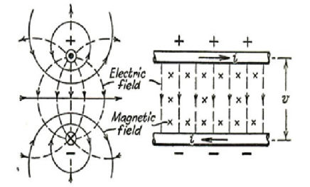
An open wire line of two conductors where the potential difference v and current i are the integrated effects of the presence of the electric and magnetic field components.
Electromagnetics of transmission lines and cables
The propagation of energy along a uniform transmission line or cable is a characteristic of the electromagnetic field in a tube of space surrounding the conductors (overhead line), or enclosed by one of them (coaxial cable).
An open wire line of two conductors where the potential difference v and current i are the integrated effects of the presence of the electric and magnetic field components.
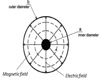
If one of the conductors is replaced by a cylindrical shell that surrounds the other conductor, the lines of the electric field now radiate outwards from the inner to the outer conductor, while the magnetic fields lines are circular.
Equivalent circuits
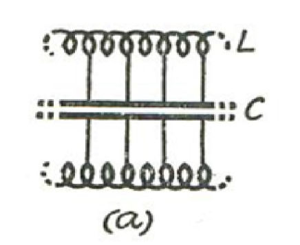
We can represent the magnetic flux per unit length, to which the current i is proportional by the product Li, where L is a distributed inductance coefficient per unit length of line. Similarly, the electric flux per unit length is given by Cv, where C is a distributed capacitance coefficient. This leads to the simple distributed L/C network (a)
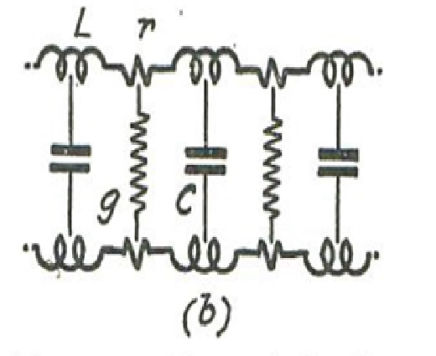
In practical circuits, the presence of current in the conductors leads to a loss i^2 r per unit length, and there is a further shunt loss v^2 g due to the leakage g per unit length corresponding to the imperfection of the dielectric medium in which the electric field exists, network (b)
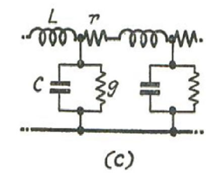
When the transmission of sustained sinusoidal signals or power is concerned, a further simplification is possible in which the inductance and capacitance are “concentrated” into one of the lines. In this way the phenomenon of signal or energy transmission may be reduced to an equivalent circuit, susceptible to solution by basic network theory, network (c)
Surge propagation in transmission lines and cables
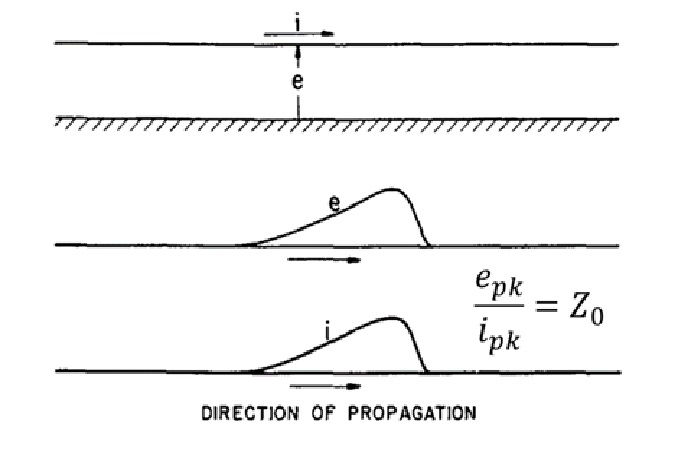
If two conductors initially dead, are suddenly connected to a supply of constant potential difference v, and electromagnetic energy wave advances along the line towards the far end at velocity u. The advancing voltage charges the line capacitance, for which an advancing current is needed; and the advance of current establishes a magnetic flux, requiring a voltage to oppose the counter e.m.f. Thus current and voltage are propagated simultaneously.
Abrupt changes such as the switching of voltage onto a transmission line will produce a voltage at the far end of the line only after a definite time delay.
Neglecting losses, then in a brief time internal dt the wave advances by a distance u.dt. The voltage is established across a capacitance Cu.dt and the rate of charge is
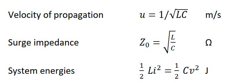
The velocity of propagation is a function of the inductance L and capacitance C per unit length, and does not depend on either the voltage and current.
L and C are functions of the geometry of the line and the properties of the ambient medium, i.e. permittivity ε = ε0 εr and permeability μ = μ0 μr
For open wires in which in which εr = μr = 1, then the velocity of propogation can be found from the permittivity and permeability of free space:
u=1⁄(√(ε0 μ0 ) = 3∙10^8 ) m/s, which is c the speed of light.
This is because the energy is propogated in the space surrounding the conductors which in this case is free air. All the conductors do is to guide the travelling waves.
The ratio v/i = Z0 is fixed by L and C, and is called the surge impedance.
The stored electromagnetic energy per unit length of wave equally divided between the magnetic and electric forms. This is a characteristic of surge transmission.
For cables, where the space between the inner and outer cylindrical conductor is filled with an insulator with εr > 1 the velocity of wave propagation is reduced, e.g. for cross-linked polyethylene (XLPE) εr ≅ 2.5 and u=1⁄(√(ε0 εr μ0 )=2∙10^8 ) m/s.
This means that surges in cables propogate at about 2/3 of their velocity in overhead lines.
For coaxial cables with multiple annular conducting layers (e.g. earth sheath, impervious sheath, and armour) with differing relative permittivities of the insulation layers between the conductors, surges will propogate at different velocities along these conductors.
Any tranmission line or cable can be characterised by two numbers, either the inductance L and the capacitance C per unit length, or the surge impedance Z0 and the velocity of propogation u. The first pair (L and C) vary considerably with changes in the dimensions of the line. In contrast to this, the velocity of propagation u is a specific constant of the insulating material used and is consequently only a function of the relative permittivity εr.
Z0 for an overhead line is typically in the range of 400 to 500 ohms, while for a coaxial structure the range is 40 to 65 ohms.
Why worry about surge propagation?