best free css templates

Satisfactory operation of power transformers in parallel

For a variety of reasons, it may be desirable to operate transformers in parallel with  each other. This may be done simply to provide additional load-handling capability to an existing overloaded transformer, or it may be by initial design to afford additional system reliability, anticipating that one transformer may on occasion be unavailable at some time such as during scheduled maintenance activities.

The satisfactory operation of transformers connected on both sides in parallel requires careful consideration of:


a)    the polarity of connections,

b)    the phase sequence (for two three-phase units),

c)    phase displacements (i.e. vector group for three-phase transformers),

d)    voltage ratio, and

e)    the individual transformer per unit impedances.


Mobirise

Each of these points and their relative importance is discussed and illustrated by simple simulation examples in the following paragraphs.


Polarity

This can either be right or wrong. If it is wrong, it results in a dead short circuit.

This is illustrated for the two single phase transformers case in the diagrams below.

Mobirise
Phase sequence and relative phase displacement

This question only arises with polyphase transformers.

Only a few of the possible connections can be worked in parallel without excessive circulating current at light load; for example, the secondary voltages of star/star and star/delta transformers have a phase difference of 30 degrees, making parallel connection impossible. The various connections can produce various voltage magnitudes and phase displacements: while voltage magnitudes can be adjusted by tappings, phase divergence cannot be compensated.

The phase sequence must be identical for two paralleled transformers. If three secondary terminals a1, b1, c1 of transformer 1 are to be paralleled with a2, b2, c2 of transformer 2, the polarity and ratio being correct, then a1 may be connected to a2. If the result is a potential difference across b1 b2, or c1 c2 then the two phase sequences differ.

Mobirise


The following are typical of the connections for which, from a viewpoint of sequence and phase divergence, transformers may be connected in parallel: 

    Transformer 1:    Yy0    Yy6    Dy1    Dy11     Dy11  

    Transformer 2:    Dd0    Dd6    Yd1    Yd11    Yz11

Thus all transformers in the same phase group (I, II, III, or IV) in the table above can be paralleled.

Mobirise

Further, transformers with a +30⁰ and a -30⁰ angle can be paralleled by reversing the primary and secondary phase-sequence of one of the transformers.  

In general, the transformers of groups III and VI can be paralleled by reversing the phase sequence of one of them. For example, a transformer with Yd1 1 connection (group VI) can be paralleled with one having Dy1 connection (group III) by reversing the phase sequence of both primary and secondary terminals of the Dy1 transformer.

Paralleling two transformers with one in group I and the other in group III is not possible.  For example delta-delta to delta-star transformer paralleling should not be attempted.


Voltage ratio 

Equal voltage ratio (not necessarily precisely the same as equal turns ratio) is necessary to avoid no-load circulating current when transformers are in parallel on both their primary and secondary sides. Since the leakage impedance is generally low to avoid regulation issues, a small voltage difference may cause considerable no-load circulating current and additional I squared R loss.

On load the circulation is masked, but may cause over-current on one transformer when the paralleled group is loaded to the full combined rating.

Note that identical transformers with tappings in the HV winding, will have different voltage ratios if their tap positions are different.


Mobirise


The diagram above shows that operating paralleled transformers on different ("staggered") tappings is a way of absorbing reactive power at the point of the network where the transformers primary windings are connected.


Leakage impedance

The leakage impedance of transformers required to operate in parallel may differ in magnitude and in quality (i.e. in the X/R, reactance to resistance ratio). It is necessary also to distinguish between per-unit and ohmic impedance; the currents carried by two transformers are proportional to their ratings if their ohmic impedances are inversely proportional, and the per-unit impedances equal on those ratings.

In practice this means that to share load current in proportion to the transformer rating, the per unit impedances must be equal when expressed on the individual transformers MVA rating as shown below.

Mobirise


A difference in the quality of the per unit impedance results in a divergence of phase angle of the two currents, so that one transformer will be working with a higher, and the other with a lower power factor than that of the combined output.

Mobirise


Summary


The satisfactory operation of transformers connected on both sides in parallel requires that they must have:

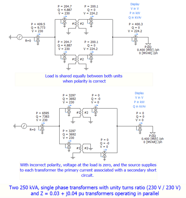
a)    the same polarity

b)    the same phase sequence (for two three-phase units)

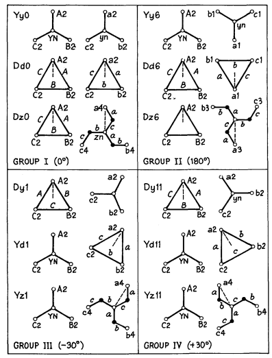
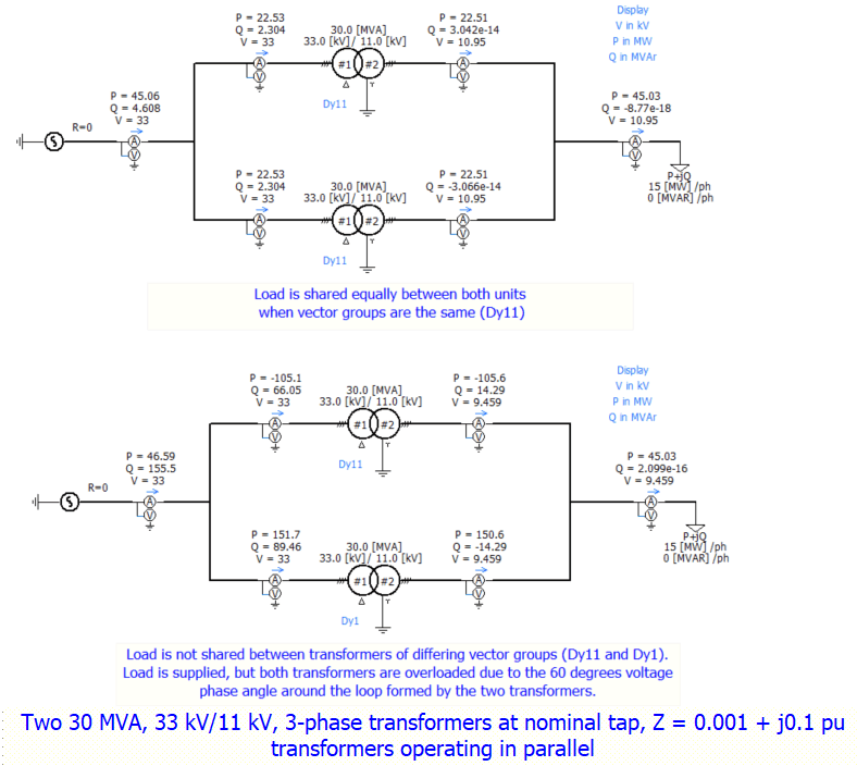
c)    zero relative phase displacements (i.e. the same vector group)

Both transformers must be from the same Group (I, II, III or IV), or one transformer from Group III and one from Group VI with the primary and secondary phase sequence of one of the two transformers revered.


Furthermore, it is desirable that they have:

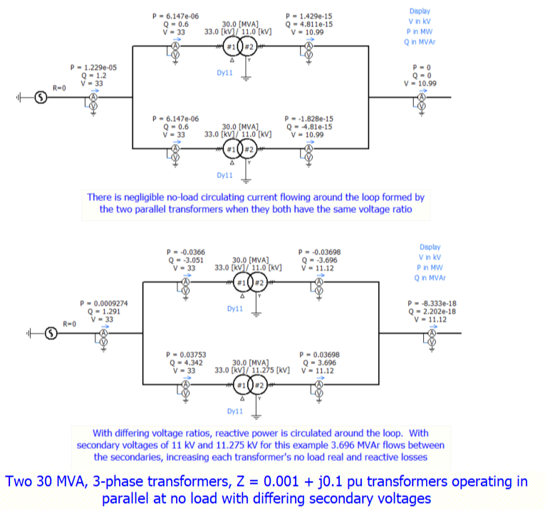
d)    a near identity of voltage ratio (tap changers should have tap positions giving voltage ratios as close as possible), and

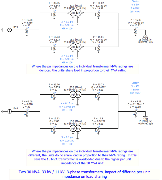
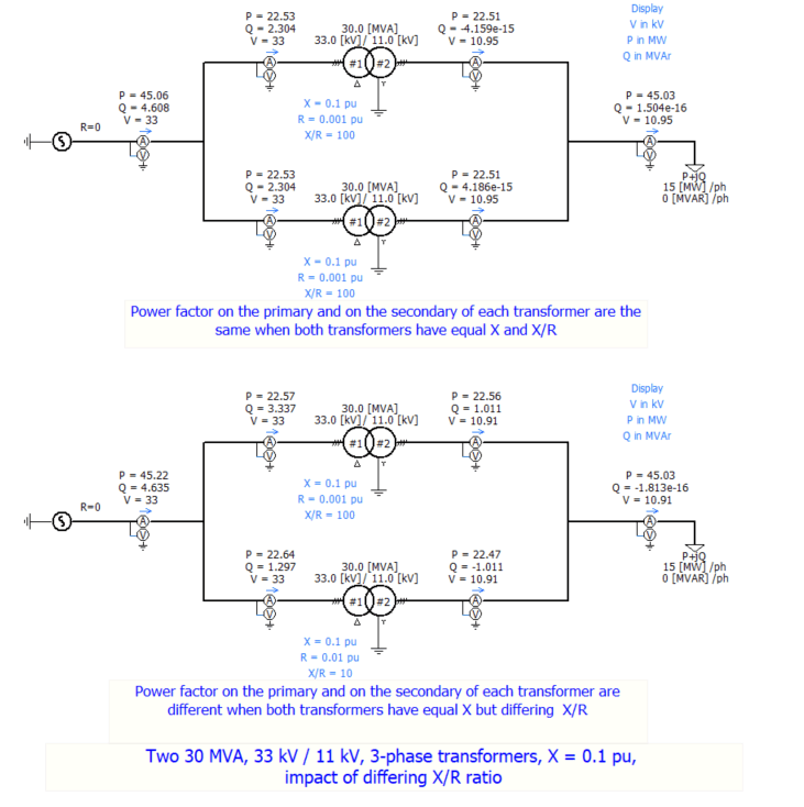
e)    a limited disparity in their per unit impedances (per unit impedance expressed on the respective units own MVA base) and quality (X/R ratio).  Plus or minus 10% is normally considered acceptable.


Items (a), (b), and (c) are mandatory for satisfactory operation.  


Any departure from equality in items (d) and (e) may lead to an uneconomical division of current, or a circulating current, both of which will lower the efficiency and the decrease the maximum safe load which the parallel units can carry.

In general it is not good practice to operate transformers in parallel under the following conditions.

1.    When the division of load is such that, with a total load equal to the combined MVA rating, the load current flowing in any one of then exceeds 110% of its normal full load.

2.    When the no-load circulating current in any transformer exceeds 10% of the rated full load value.

3.    When the arithmetic sum of the circulating current and load currents is greater than 110% of the normal full-load current.

In the above, circulating current is understood to be the current flowing at no load in the primary and secondary windings excluding the magnetizing current. By load current in meant the currents flowing in the transformers under load, exclusive of exciting and circulating currents.

All of this depends on the loading profile, the duration of peak load, and the thermal dissipation characteristics of the transformer. Nevertheless, these limits, proven by experience, provide valuable guidance when equality in items (d) and (e) is not achieved,


Notes:

1.    Here we have considered the conditions necessary for parallel operation of two or more two winding transformers (i.e. transformers with primary and secondary windings) assuming there are no other system constraints to consider.  In practice, the increase in total MVA transfer between two busbars by the addition of a parallel transformer will change other system parameters such as fault level and resonant frequency all of which will require analysis when considering the use of additional parallel transformers.

2.    The parallel operation of two three winding transformers (i.e. where the transformers have primary, secondary and a tertiary "third" winding) is a more complex case.  Furthermore the parallel operation of a two winding transformer with a three winding transformer is in most cases unsatisfactory.


Further information

L.F. Blume, etc all, Transformer Engineering - A treastise on the theory, operation, and application of transformers, 1st Ed, Chapman and Hall, 1938.

Central Station Engineers - Westinghouse Electric Corporation, Electrical Transmission and Distribution Reference Book, 4th Ed, 1964.

M.G. Say, Alternating Current Machines, 4th Ed, Pitman, 1976.


Disclaimer

The information presented in this technical note is for educational purposes only. 

K S Power Consulting Ltd. disclaims any responsibility and liability resulting from the use and interpretation of this information.


 By using this website you agree to our Terms of Use and Privacy Statement
K S Power Consulting Limited is a registered company in Scotland
Company number SC620114
Registered Address: 8 Douglas Street, Hamilton, ML3 0BP