how to build a website

What determines the reactance of a transformer ?

At one time the reactance of a transformer was considered to be an imperfection creating regulation (voltage drop) due to the unavoidable existence of leakage flux. It is now recognised that transformer reactance is an invaluable tool for the system designer enabling him to achieve system fault levels to meet the economic limitations of the switchgear and other connected plant.

Consequently, it is often necessary for power system analysis engineers to specify the impedance (which is almost equal to the reactance since the resistance is much smaller) of a new transformer considering existing power system constraints such as fault levels or voltage drop requirements (e.g. when starting large motors). In this regard the impedance is simply a value in a model which satisfies the system constraints, i.e. the transformer is effectively a two terminal device (with primary and secondary connections) with a specific impedance.


In this short note we look at the distribution of the leakage magnetic flux within the transformer and how this distribution is influenced by the dimensions of the transformer windings.

It is this internal distribution of leakage flux that determines the inductive reactance of the transformer as measured during a short circuit test.

Mobirise

The calculation of transformer leakage flux is a prerequisite to the calculation of reactance, short-circuit impedance, short-circuit forces, and eddy current losses.


Leakage flux effects in transformers

The flux plots show typical flux leakage patterns in one limb of a transformer (in these plots the upper half of the winding is considered, the hatched area is the iron core of the transformer).

These are simplified drawings and it should be remembered that magnetic flux lines always form closed loops, in contrast to electrostatic flux lines which radiate from one point to another.

In a) with concentric cylindrical primary and secondary windings of equal length, the leakage flux runs parallel to the axis for nearly the whole length of the windings.

In b) the windings are of unequal lengths, and the field is significantly modified.

In both cases, near to the winding ends, the leakage flux bends towards the core, making shorter its return path. In this region the leakage flux has both axial and radial components.

Mobirise

We can simplify the field geometry to obtain straightforward approximate estimates of the field pattern. The leakage flux is considered as the superposition of straight components in one or two directions. 


Reactance of concentric cylindrical shells of equal length

In this discussion we will focus on case a) in the above diagram where the winding heights are equal.

The leakage field is taken to have two components, an axial flux

(i) of uniform and constant value in the interspace region between the primary and secondary, and

(ii) a value decreasing linearly to zero at the outer and inner surfaces of the windings and threading through them.

The permeance (i.e. the reciprocal of reluctance) of the leakage path external to the winding length Lc [m] is taken to be so large as to require negligible m.m.f. In other words, the whole of the combined winding m.m.f. is expended on the path Lc.

In addition it is assumed that there is primary and secondary m.m.f. (i.e. Ampere-turns) balance. The flux density in the duct of width a and the duct flux can then be calculated as shown where Lmt is the mean circumference of the duct, which is nearly the same as the length of a primary or secondary turn.

Mobirise

Here we now refer to the inner winding closest to the core as the primary winding.

Half of the flux in the duct is taken as linking the N1 primary turns to give the primary flux linkage.

Mobirise

In the adjacent diagram F is the ampere-turns enclosed by a circle centred on the core centre with radius equal to the inner radius of winding 1 plus x. The mmf at any point depends on the ampere-turns enclosed by a flux contour at that point. The ampere-turns increase as x traverses the inner winding, is constant in the duct, and decreases across the outer winding due to the opposing polarity of the currents in windings 1 and 2.  The ampere-turn distribution across the cross section of the windings is of a trapezoidal form.

Mobirise

Within the primary winding at a radial distance x from its inner surface, the incremental flux in an elemental annulus of width dx and (approximate) circumference Lmt can be found.

As the incremental element links only the fraction (x ⁄ b1 ) of the turns, integrating over the width b1 gives the total internal flux linkage.

Summing the external flux in the duct and the internal flux gives the total primary winding flux linkage. 

Mobirise


The primary leakage inductance L1 is the winding flux linkage per ampere.

For a primary current of 1 A, the duct flux density can be found and from this the primary winding inductance. 

Mobirise


Substituting N2 for N1 and b2 for b1 will give the secondary leakage inductance L2.

Mobirise


The total equivalent inductance in primary terms (i.e. referring the secondary to the primary by the turns ratio squared) is easily found.

Mobirise

The corresponding ohmic value of the leakage reactance referred to the primary winding at frequency f [Hz] is obtained by multiplying the total equivalent inductance referred to the primary by the equivalent angular frequency.

Mobirise

Alternatively, with F as the rated m.m.f. (ampere-turns) per limb at rated primary current I1, and Et the e.m.f. per turn (rated primary voltage V1 divided by the number of primary turns N1), an expression for the primary turns squared can be derived.

In this expression Zb is the base impedance of the winding defined by the primary rated voltage V1 and rated primary current I1.

Mobirise

This expression allows both the per-unit and percentage reactance of the winding on its volt-ampere rating to be determined in terms of F the rated ampere turns and Et the voltage per turn, which are the two basic design parameters of the transformer.

In general this percentage value of the leakage reactance usually ranges between 4% and 22% of the base transformer rating (see graph below).

Mobirise

These equations for per unit or percentage reactance are much more useful to the transformer designer since they are based on the basic design parameters of full load current Ampere-turns and voltage per turn, both of which parameters are the same for both windings, therefore the reactive volt-amperes of a transformer are the same whether reckoned in terms of primary or secondary windings, in contrast to the ohmic value which varies as the square of the turns ratio, and the reactance voltage which varies as the first power of the turns. 

More complex equations can be derived for cases where the height of the two windings differ i.e. case b) in the diagram above, and instead of using only the mean circumference of the duct, the mean circumference of the primary winding, duct, and the secondary winding can be incorporated into the formulae. As early as 1909, Walter Rogowski had devised additional correction factors to these extended equations by solving the Laplace and Poisson equations using a single Fourier series which improve the accuracy of the reactance calculation.

The equations here demonstrate the more advanced Rogowski method applied to the geometry previously shown above.

In these equations db1, da, and db2 are the mean diameters associated with regions b1, a, and b2, while Hw is the winding height. These factors determine A which is a coefficient used in the calculation of the Rogowski factor Kr. In most practical cases the numerical value of Kr is within the range 0.95 to 0.99.  This factor is used to convert the actual winding height to an equivalent height Heq.   The Rogowski factor makes the length of the leakage field in the duct a little longer.  Ad is the area of the Ampere-turn diagram. 

Mobirise

When there are more than two windings per limb the leakage reactance between any two pairs of windings can be found assuming that all other windings behave like a gap.

It is interesting to compare the two alternative calculation methodologies. For the 31.5 MVA, 50 Hz, 132 kV/11 kV, Yz (star zig-zag) transformer shown, with 76.39 V/turn, the percentage leakage reactances (on 31.5 MVA) calculated using the two different approaches are as tabulated.  

Mobirise

As the Rogowski method increases the effective winding length, the calculated leakage reactances are slightly reduced.

Due to the significant impact of transformer leakage inductance on power electronic converters, more than 100 years after the publication of Rogowski’s work, researchers are still deriving new and innovative methods for leakage reactance calculation.


How do the winding dimensions and spacing influence transformer reactance? 

As mentioned in the introduction, it is often necessary to specify the reactance of a new transformer based on existing power system constraints such as fault levels or voltage drop requirements. The transformer designer can meet these particular system requirements of the transformer reactance in different ways.

Recall the basic voltage per turn design equation for a transformer for operation at frequency f [Hz], with Bmax the peak core flux density (T or Vs/sq m), and Acore the effective cross-sectional area of the core [sq m].

Mobirise

Consider a three-limb transformer with a fixed rated core flux density, where C is the distance between the core limb centres, D is the core circle diameter, and L is the length of the core limb which is approximately the winding length.

Using the voltage per turn equation and that derived above for the per unit reactance of the transformer, for a given transformer kVA rating and primary and secondary voltages, with no significant change in the core frame dimensions, the reactance proportionality is found to be as shown in equation (a).

Where the frame size is varied to the extent that the mean turn length is affected considerably, the reactance proportionality is given by equation (b) 

Mobirise

Inspection of all these alternative equations for reactance show that:

1)    The size of the winding cross-sections influences the reactance. The reactance can be controlled by varying the dimensions of the core, the windings, and the gap between the windings.

In simple terms, if the space between the high voltage and low voltage windings is kept large, there will be more flux lines contained in the space between the high voltage and low voltage winding, which will increase the leakage reactance. 

2)    Increasing the height of the windings will reduce the leakage reactance.

In simple terms, a tall transformer gives a low impedance and visa-versa.

This is illustrated for a 31.50 MVA, 132 kV/33 kV, Yd1 transformer in the adjacent graph.  At the “design” value for winding length and the gap between the LV and HV windings the leakage reactance is 14.63% (Rogowski method).

Varying only the winding height (blue curve), increasing this by a factor of 1.200 decreases the reactance by a factor of 0.841 times; the reactance is now 12.31%.

Varying only the gap between the LV and HV windings, increasing this by a factor of 1.200 increases the reactance by a factor of 1.102; the reactance is now 16.14%. 

Mobirise


Other factors that need to be considered

Although the designer has some scope to provide the system required reactance there are other constraints on the transformer design.

If the leakage reactance values are too high, it can increase the eddy current losses in the windings and stray losses in the structural parts of the transformer.

If the leakage reactance value is too low, it can result in higher electromagnetic forces and short-circuit current. In both cases, the use of the extra cooling or increase in the copper content that will be needed, can result in a higher overall cost for the transformer.

The calculation of reactance occurs relatively late in the overall design process as shown in the sequence of design steps.

The short-circuit impedance of the transformer influences both the production and capitalised costs (the latter also taking account the capitalised cost of the in service losses). 

Mobirise

Minimum short circuit impedances for transformers rated at 100 MVA or less are given in IEC 60076 as shown here. These are largely based on ensuring the transformer has sufficient impedance (i.e. reactance) such that the windings can withstand the mechanical forces generated during a short circuit at rated voltage.

Mobirise

The short circuit current flows through the winding conductors, which are situated in the magnetic leakage field. As a result of this the conductors are subjected to mechanical forces. These forces are not static and pulsate.

At the normal load current the forces are small. The forces increase with the square of the current (as the flux density B is proportional to current I, and the force on a conductor carrying current I in a field of flux density B is the product of B and I), so the high currents that occur during a short circuit which may be 10 to 20 times the rated current of the transformer result in forces in the windings which may be 100 to 400 times larger than when in normal service.

Mobirise

As mentioned above at the top and bottom ends of the windings, the main leakage flux has both axial and radial components.  The axial component of the leakage flux density interacts with the  current in the windings, producing a radial force responsible for the axial repulsion between the inner and outer windings.  The radial flux component interacts with the winding current, producing an axial force which acts in such a way to produce an axial compression or expansion of the winding coils.

Buckling (the bulging inwards and outwards) or spiralling (the tightening up to a smaller diameter) of the winding conductors will occur if its bracing is not sufficient to withstand the mechanical forces experienced during a short circuit.

In addition, transformer designers have to fulfil the maximum tolerance limit of international standards such as IEC 60076- 1 and ANSI/IEEE C57.12.00. Manufacturing tolerances in impedance values need to be considered for design purposes. This is the tolerance permitted on contracted (guaranteed) impedance to the actual measured (tested) impedance. IEC Standard 60076-1 presently allows: 

 ±10% tolerance for transformers with an impedance less than or equal to 10%

 ±7.5% tolerance for transformers with an impedance greater than 10%.

The graph shown gives typical impedance values for a range of transformer ratings which may be found in transmission and distribution systems. It should be recognised that these are typical only and not necessarily optimum values for any rating.   

Mobirise

Note however two general trends in this graph:

1) for a fixed voltage the impedance increases with MVA rating, and

2) for a fixed MVA rating the impedance increases with voltage.


Impedances varying considerably from those given may well be encountered in any particular system.


Summary 

While a power system study can be used to determine the required impedance of a new transformer i.e. a value which leads to satisfactory results from running power system studies, reactances that are significantly different from the minimum short circuit impedances for transformers given in IEC 60076 i.e. “standard values” may be problematic for the transformer designer.

The reactance of a transformer can be controlled by varying the dimensions of the core, windings, the gap between the windings and the height of the windings.

Increasing the size of the gap between the winding cross-sections increases the transformer reactance, while increasing the height of the windings will reduce the reactance.

The transformer designer has to balance reactance changes with the risk of higher eddy current loss with high reactance designs, or poor mechanical short circuit withstand capability with a low reactance design.

Power system analysis engineers when specifying the required reactance of a transformer determined from a series of power system studies should be aware of the practical limits imposed on transformer design by the geometric arrangements of the windings as outlined in this brief note.  The graph above giving typical impedance values for a range of transformer ratings is a useful guide to what impedance and hence reactance can be achieved in practice.

Notes

1. A common modelling assumption is to assign half of the total leakage reactance of a two winding transformer to each side of the transformer equivalent circuit. Inspection of the equations for the individual winding inductances L1 and L2 given above, show that this assumption is only valid in the case where b1 the radial width of winding 1 is equal to b2 the radial width of winding 2.

2. In this note we have considered the reactance of a single phase transformer, and the reactance (positive sequence) per phase of three phase core type transformers. The zero sequence reactance of thee phase core type transformers requires a more complex calculation.

3. The leakage reactance of a transformer is essentially the series reactance between the primary and secondary windings. As this is associated with the leakage flux in the air gap it is independent of the level of core saturation. Under normal operating conditions at rated voltage the magnetizing current is very small compared to the rated load current i.e. the shunt magnetizing reactance is very large. Under certain conditions such as energization, the transformer the core cannot carry the required flux due to magnetic saturation. In this situation it is the air cored reactance of the energised winding which is required.

The calculation of the air cored inductance using the classical equations for either a “long” or "short" solenoid can lead to errors.


A good estimate of the air cored inductance of a winding (i.e. with the core removed) can be made using the equation show here, where with all dimensions in metres:

Dm is the mean diameter of the winding
N is the number of turns
H is the winding height
a is the winding thickness.


Mobirise


Further information

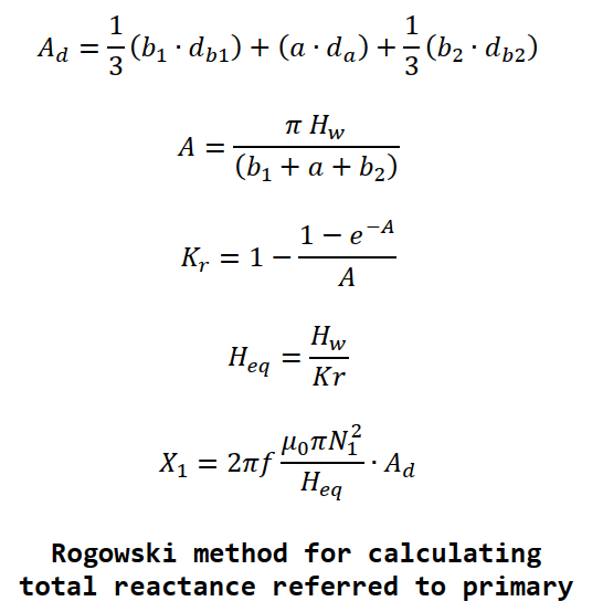
W. Rogowski, “Über das Streufeld und den Streuinduktionskoeffizienten eines Transformators mit Scheiben-Wicklung und geteilten Endspulen,” Verein Deutscher Ingenieure, Mitteilungen über Forschungsarbeiten, Heft 71, Berlin, 1909.

L. F. Blume et al, Transformer Engineering - A treatise on the Theory, Operation and Application of Transformers, John Wiley, Chapman and Hall, 1938.

S Austen Stignat, H Morgan Lacey, J & P Transformer Book, 8th ed, Johnson & Phillips, 1941.

D. McDonald, Power Transformers for high-voltage transmission with special reference to their design, Bruce Peebles and Co. Ltd., 1957.

M. G. Say, Electrical Engineering Design Manual, 3rd ed, Chapman and Hall, 1964.

M. Waters, The Short-Circuit Strength of Power Transformers, McDonald & Co. Ltd, London, 1966.

M.G. Say, Alternating Current Machines, 4th ed, Pitman, 1976.

R. Feinberg, Modern Power Transformer Practice, Wiley, 1979.

K. Karsai et al, Large Power Transformers, Elsevier, 1987.

M. Heathcote, J & P Transformer Book, 12th ed, Newnes, 1998.

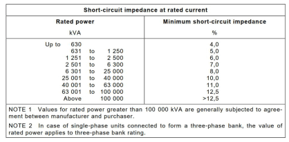
IEC 60076-5, Power transformers – Part 5: Ability to withstand short circuit, 2000

S.V.Kulkarni, S.A.Khapardem, Transformer Engineering Design and Practice, Marcel Dekker, 2004.

G. Bertagnolli, Short-circuit duty of power transformers, ABB, 2006.

Disclaimer

The information presented in this technical note is for educational purposes only.
K S Power Consulting Ltd. disclaims any responsibility and liability resulting from the use and interpretation of this information.

 By using this website you agree to our Terms of Use and Privacy Statement
K S Power Consulting Limited is a registered company in Scotland
Company number SC620114
Registered Address: 8 Douglas Street, Hamilton, ML3 0BP